ECE 2A:
Circuits, Devices, and Systems
Fall
2010
Breadboards
The best method of experimenting
with ICs is to use a "breadboard" to build circuits. Breadboards,
more formally known as solderless
modular sockets, get their name from the early days of radio, when
it was common to build vacuum tube circuit prototypes on a wooden breadboard.
Today's breadboards are a
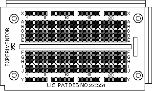
grid of insulating plastic atop a pattern of conducting metal strips. Here is a
top view of a typical breadboard:

Component leads and wires
are inserted into the holes and make contact with the conducting metal strips
underneath, thus "connecting" them together.
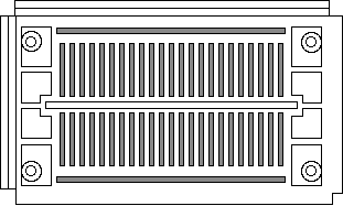
The pattern of conducting
strips underneath the insulating plastic is shown below. Notice there are two
horizontal strips along both sides of the breadboard and a series of shorter
vertical strips. The two horizontal strips are normally used for power supply
connections, with one strip being the supply voltage and the other being the
ground connection. (Breadboards with four horizontal strips are available, and
are used for circuits requiring dual polarity or multiple voltage power
supplies.) The horizontal strips are often known as rails.

Note the gap separating
the vertical strips. The dual in-line package (DIP) IC is normally placed
across this gap. One row of pins is one side of the gap, and the other row of
pins is on the opposite side.
Breadboards come in a
variety of sizes, and are usually measured in terms of the number of connection
or "tie points" provided. Some breadboards come with binding posts
for connecting a power supply; deluxe models have power supplies built in and
with additional supports for potentiometers, LEDs, and meters.