ECE 2A:
Circuits, Devices, and Systems
Fall
2010
HEATSINKS:
Power
and heat
Heatsink characteristics
Making heatsinks
Use existing heatsinks
Mounting devices
POWER
AND HEAT
Any device carrying a current and
simultaneously a voltage drop across its terminals is dissipating power,
tending to increase its temperature. How hot the device gets is
determined by the package and its environment. In some low-power applications,
natural convection to the surrounding air and/or thermal conduction through the
device leads may be sufficient to keep the device at a safe operating
temperature. For power dissipation of 0.5W or higher, we need to consider
the thermal problem carefully. The safe operating temperature of a device
and/or maximum power dissipation levels will be specified in the data
sheet. Most device are fairly robust in the short term, but long term
reliability is adversely impacted by operation at elevated temperatures.
Typically a transistor or IC must be operated at an internal temperature of
< 150C, which often translates to a case temperature of <100C.
Consider the power-supply that we make
in ECE 2. This is designed to put out around 9-12V at 0.2 A.
However, the input DC voltage to the regulator circuits (coming from the
full-wave bridge rectifier) may be as large as 18V, depending on the
transformer. Thus the regulator must drop around 6-9V, so at the maximum
current level the device will be dissipating 1.2-1.8 Watts. We can
manage this thermal dissipation with a heat-sink.
HEATSINK
CHARACTERISTICS
IC packages and heatsinks are
characterized by a so-called "thermal resistance", with units of
°C/Watt, that essentially reduces a thermal problem to a simple equivalent
electrical circuit. The rate of thermal energy dissipation (in Watts) is
analogous to a current flow, and the temperature drop is analogous to a voltage
drop. A TO5 transistor (for example) without a heatsink has a package-related
thermal resistance of somewhere in the region of 220°C per watt. So for every
watt dissipated it will increase its temperature by 220°C, or about 240 - 250°C
at normal room temperatures. That's hot enough to melt solder! But a
clip-on heatsink with a characteristic of 40°C/W will limit that device to 40°C
+ 25°C (room temperature) = 65°C. With the heatsink the transistor will
therefore survive. The heatsink simply conducts heat away from the device and
dissipates it into the room, so the larger the surface area, the lower (better)
the °C/W rating that heatsink has.
Now lets apply this idea in
reverse. Suppose you have a device that is dissipating 1 Watt, and you
need to keep the case temperature below 75C. If room temperature is 25°C,
that means the allowable temperature rise above ambient is 50°C. So we
need a heatsink with a thermal resistance of 50°C/1W=0.5°C/Watt. Most
suppliers catalogues give a heatsinks °C/W characteristic.
MAKING
HEATSINKS
You can evaluate home-made heatsinks
by using the following 'ROUGH' formula:
![]()
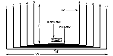 As an example, let us
make a heatsink with 18 SWG aluminum sheet, folded as shown. The heatsink is
going to be 20cm wide (W), 10cm deep (D) and 12cm high. Each 'fin' is 10cm x
12cm = 120cm. Each fin also has two sides, area = 240 square cm. There are 10
fins so we have a total of 2400 square cm. The rear plate is also 2 sides x
20cm x 12cm = 480 square cm. Total area = 480 + 2400 = 2880 square cm.
Since the square root of 2880 = 53.66 we therefore have 50/53.66 =
0.932°C/watt.
As an example, let us
make a heatsink with 18 SWG aluminum sheet, folded as shown. The heatsink is
going to be 20cm wide (W), 10cm deep (D) and 12cm high. Each 'fin' is 10cm x
12cm = 120cm. Each fin also has two sides, area = 240 square cm. There are 10
fins so we have a total of 2400 square cm. The rear plate is also 2 sides x
20cm x 12cm = 480 square cm. Total area = 480 + 2400 = 2880 square cm.
Since the square root of 2880 = 53.66 we therefore have 50/53.66 =
0.932°C/watt.
It is also common practice to use the
enclosure or chassis of a unit as the heatsink. An aluminum box 5cm x 10cm x
20cm would therefore have an OUTSIDE surface area of 5 x 10 x 20 = 1000 square
cm. Square root of 1000 = 31.623 so our equipment case has a thermal
dissipation of (50/31.623)°C/W = 1.58°C/W Since we need 1.13 we do not have
enough, but we can use the case to cut down the size of the heatsink we need.
Notice that the inside of the case was not taken into account. The case is a
closed box so without ventilation the inside of the case will dissipate
nothing.
MOUNTING
DEVICES
Almost all devices that we need to
mount on a heatsink have a metallic surface from which the heat is to be
conducted. This surface is usually electrically connected to one of the
terminals of the device. So for a direct connection to the
heatsink, the heatsink itself will acquire whatever voltage is at that device
terminal. If the terminal is grounded that may not be a problem, but
otherwise we need to place a thin insulator between the device and the heat
sink. In the case of transistors this is in the form of a mica washer or disk,
which is a decent thermal conductor but not an electrical conductor.. The disk
is lubricated with thermal oil or paste to improve heat transfer. The oil and
the washer should never be omitted if the device is to be electrically isolated
from the heatsink.