Difference between revisions of "Thermoreflectance"
From OptoelectronicsWiki
(→Measurement Procedure) |
(→Measurement Procedure) |
||
| Line 22: | Line 22: | ||
##Input current you went up to in step 3 (right-hand side of window) | ##Input current you went up to in step 3 (right-hand side of window) | ||
#Custom string does work if you’d rather use a different power supply, but it has to have address 6 | #Custom string does work if you’d rather use a different power supply, but it has to have address 6 | ||
| + | #Turn image shift on and make sure the ROI is somewhere with a lot of clear edges. This solves some issues relating to vertical shifting during heating/cooling. | ||
#Start calibration by hitting “start acquisition” button | #Start calibration by hitting “start acquisition” button | ||
#It takes a couple cycles for minimum and maximum temperatures to reach actual values. Keep track of thermocouple read-out and only take data from points where this is consistent. Change in temperature box can be updated while measurement is going on. | #It takes a couple cycles for minimum and maximum temperatures to reach actual values. Keep track of thermocouple read-out and only take data from points where this is consistent. Change in temperature box can be updated while measurement is going on. | ||
#When image is converged, enter file name and click “save image.” This will save the image from exactly one heating/cooling cycle. | #When image is converged, enter file name and click “save image.” This will save the image from exactly one heating/cooling cycle. | ||
| + | #Inspect image in ThermoView for the following: | ||
| + | ##Calibration coefficient on the order of 1e-4. 1e-3 is indicative of shifting during calibration | ||
| + | ##Calibration coefficient is the same for the same material everywhere. It need not be identical pixel-by-pixel, but an averaged region on the top of the image should give you the same value as an averaged region at the bottom. | ||
| + | ##Calibration coefficient on already-calibrated materials matches already-calibrated values. | ||
#If you believe the results, record Cth values in log book (on desktop of thermal imaging computer) | #If you believe the results, record Cth values in log book (on desktop of thermal imaging computer) | ||
#Turn off LED, CCD, and TEC | #Turn off LED, CCD, and TEC | ||
Revision as of 16:41, 18 November 2011
Operating Principle
Basic Operation
Calibration
Measurement Procedure
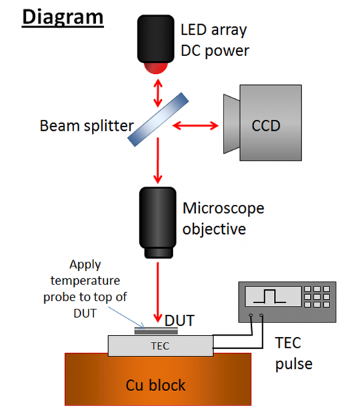
- Position device on stage, place thermocouple on top of device
- Hook LED array up to DC current source
- Current less than 1000mA for NIR, 1600mA for blue and green
- Hook TEC to Agilent power supply, apply 200mA current (or other depending on application) (<1V). Keep temperature below 60C.
- Agilent power supply must have GPIB address 6
- This is a bug, it should be fixed in future software
- Microsanj pulse generator should not be on during calibration
- Agilent power supply must have GPIB address 6
- Wait for temperature to reach steady state, record T (again, <60C). ~5 degrees C change is ideal for this.
- Turn power supply off. Wait for temperature to reach steady state. Record time and temperature
- Turn on Microsanj transient imaging module
- Open ThermoVIEW (not cal) and check image to make sure it is in focus and CCD is not saturated.
- Close ThermoVIEW. If ThermoVIEW does not close properly, calibration software will not work (restarting computer solves this problem)
- Open ThermoCAL. Input image average (default OK), temperature change recorded from steps 4-5
- If device is heated when the TEC is on, the sign should be positive
- Input thermal time constant. Make this number larger than the number recorded in steps 4-5
- Input current you went up to in step 3 (right-hand side of window)
- Custom string does work if you’d rather use a different power supply, but it has to have address 6
- Turn image shift on and make sure the ROI is somewhere with a lot of clear edges. This solves some issues relating to vertical shifting during heating/cooling.
- Start calibration by hitting “start acquisition” button
- It takes a couple cycles for minimum and maximum temperatures to reach actual values. Keep track of thermocouple read-out and only take data from points where this is consistent. Change in temperature box can be updated while measurement is going on.
- When image is converged, enter file name and click “save image.” This will save the image from exactly one heating/cooling cycle.
- Inspect image in ThermoView for the following:
- Calibration coefficient on the order of 1e-4. 1e-3 is indicative of shifting during calibration
- Calibration coefficient is the same for the same material everywhere. It need not be identical pixel-by-pixel, but an averaged region on the top of the image should give you the same value as an averaged region at the bottom.
- Calibration coefficient on already-calibrated materials matches already-calibrated values.
- If you believe the results, record Cth values in log book (on desktop of thermal imaging computer)
- Turn off LED, CCD, and TEC
Low Frequency
Transient
Measurement Procedure
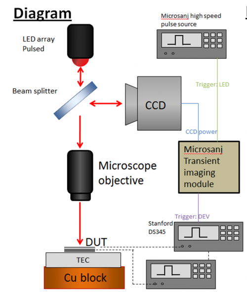
Position device on stage and probe it Turn on Microsanj Transient imaging module and high-speed signal generator
- Hook up the LED:
- Attach Trigger:LED on the transient imaging module to TRIG IN on the high-speed pulse source
- Attach PULSE OUT from the 300V pulse source (on the right of the module) on the high-speed pulse source to the LED
- Hook up the device:
- Attach Trigger:DEV on the transient imaging module to the input trigger of the Stanford Research synthesized function generator
Either:
- Attach the function:out from the function generator to the input of your device pulse source
- Attach your device pulse source to the device (check polarity on the ILX current sources)
OR attach your device directly to the function generator
- Make sure camera is attached to CCD power on the transient imaging module
- Open the ThermoVIEW software and in the Project Manager, make the following changes:
- Image type: Transient
- Use Pulse Gn. Checked (GPIB 6)
- Use Fn Gn checked (GPIB 19) if using SRS pulse generator
- Workspace path: choose something appropriate
- Adjust LED current, etc. until historgram looks good – when the “good illumination” light turns green )lower right-hand corner), click “Get Image”
- Check Voltage and Delay fields on the left hand side of the screen.
- If you are using the SRS function generator, you must change the voltage and click “update V” in order for the change to take effect
- Delay corresponds the falling edge of the LED pulse – to take an image of your device at the end of the heating cycle, set delay to the device pulse width
- Begin averaging when signals have all checked out
- Save image at the bottom of the screen when it looks converged
- Turn off LED, CCD, and TEC
Pulse setups
Current pulsing
See the ILX LDP 3811 page if you are using the ILX pulsed current source to get the correct wiring diagram.
Optical input pulsing
Manual and Guides
User Manual
- NT200t Reference Manual (PDF - 4/7/2011)
Documentation
- Thermoreflectance Imaging Guide by Xi Wang (PDF)
FAQ
If there are issues with your measurement or the tool, check whether a solution is posted below first. If you still are experiencing problems, contact Ben Curtin at [bcurtin@ece.ucsb.edu] or 773-592-9568.
Bug Tracker
List bugs/issues that haven't been resolved with this setup below. If you have a temporary fix, please include it in the "description" field. Issues will be crossed off the list once they are resolved or documentation has been updated to address them.
Major Issues
| Name | Component | Description | |
|---|---|---|---|
| NAME | COMPONENT | DESCRIPTION |
Minor Issues
| Name | Component | Description |
|---|---|---|
| NAME | COMPONENT | DESCRIPTION |
Suggestions
| Name | Component | Description |
|---|---|---|
| NAME | COMPONENT | DESCRIPTION |

